
| NEWS | |||||||
| ABOUT | |||||||
| PRODUCTS AND SERVICES | |||||||
|
| |||||||
| PLACE AN ORDER | |||||||
| DOWNLOAD | |||||||
| HELPFUL HINTS | |||||||
| FAQ | |||||||
| LINKS | |||||||
| SEARCH | |||||||
| SITE MAP | |||||||
| CONTACT | |||||||
| русский |
Compressor repair
At replacement of condensation of a shaft of the compressor or the switches of pressure established in a back cover or reducing valve first it is necessary to unload system of conditioning from therefrigerant even if repair will be made without dismantle of the compressor. Except for repair of coupling this requirement concerns to all repair work connected to disassembly of the compressor. If the back cover of the compressor is subject to repair, preliminary it is necessary to merge oil to measure and write down its volume, and then to replace anew in the same amount. Beforehand it is important to prepare a workplace, to lay clean sheets of paper, to arrange pallets for details etc. It is necessary to use only clean tools. Attention: Application of any improvised and inappropriate adaptations and tools may result in damage or poor-quality repair and unsatisfactory work of the compressor.
| ||||||||||||||||||||||||||||||||
|
Border condensation of a shaft of the compressor.
At presence of a small amount of oil on surfaces of details condensation is not replaced. The design of collar condensation provides small infiltration of oil for greasing a working sealing edge. Condensation is necessary to be replaced at occurrence of a significant amount or oil splashed or at detection of outflow of the refrigerant. At replacement of condensation of a shaft of the compressor simultaneously it is necessary to dismantle a receiver from the automobile, to merge oil from it, to measure amount of oil and to replace it with fresh one.
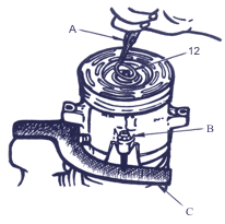
Necessary adaptations: nippers for installation of spring rings, a stripper for sealing rings, the connecting adaptation, the assembly adaptation for collar condensation, the assembly adaptation for sealing rings, the protective adaptation for condensation.
For replacement:
- It is necessary to unload the system of air-conditioning from the refrigerant.
- To dismantle from the automobile the compressor and to set it up on an arm in a vice.
- To remove a driven coupling disk of 8 with a nave. To remove a lock ring of condensation - 12 with the help of nippers - A.
- To carefully clean an internal cavity of the compressor in which there is an end of a shaft, including a shaft, condensation 13, and a flute of a sealing ring. Hit of a dirt into the compressor may put it out of action.
- To insert against the stop the adaptation - B shaft with a notch - A into an aperture of condensation and to turn it clockwise. With rotating-forward movement, to dismantle condensation from crack case of the compressor. Further this condensation is impossible to use. Dismantle of condensation is made manually, it is forbidden to apply nippers or keys.
- With the help of a stripper - A to dismantle a sealing ring 14.
- To carefully clear a flute of a sealing ring in crack case of the compressor.
- Repeatedly
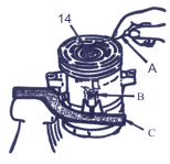 to check up cleanliness of a shaft and a cavity of the compressor and absence of products of deterioration of condensation before installation of details.
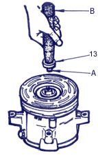
Attention: It is forbidden to establish second-hand condensation repeatedly. It is necessary to use only new condensation from the repair complete set.
It is necessary to be convinced, that the new sealing ring 14 has no cuts or other damages of a surface, and also in cleanliness of a ring and absence on it fibres which may damage condensation or cause outflow.
For installation:
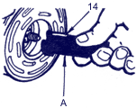
- To dip a new sealing ring 14 into refrigerating oil PAG and to put it on the assembly adaptation A.
- To insert in crack case of the compressor the assembly adaptation - A with a ring and to advance it against the stop. To lower a mobile element of the adaptation in order to establish a ring in the bottom flute of crack case. (Top flute in crack case is intended for installation of a spring ring). To turn the adaptation for landing a ring in a flute, then to take out the assembly adaptation - B.
- To
 establish collar condensation 13 on the assembly adaptation and to dip into pure refrigerating oil of mark 525 if system KB is filled with refrigerant R-12, or in oil –јG if a working body of the conditioner is refrigerant R-134a. To establish in a cuff protective device - A. Put on the device on a shaft and with rotary movement to establish condensation 13 in a jack.
 - With the help of nippers for installation of spring rings to establish in an aperture of crack case a lock ring 12. The flat side of a ring 12 should be inverted to condensation 13. With the help of the cartridge to move a persistent ring up to an assembly flute so that the ring was reliably fixed in it.
- To check up tightness of condensation. To establish on a back cover of the compressor armature for the control of tightness and to connect pipelines from manometers.
- To check up tightness of condensation. To establish on a back cover of the compressor armature for the control of tightness and to connect pipelines from manometers.
- To check presence of outflow and at detection to remove. To remove a nut 11.
- To remove the excessive oil which has got on a shaft and in a cavity of crack case during installation.
- To establish on a place a pulley.
- To fix the compressor to an arm of the engine and to put on a driven belt.
- To pump out air from KB system and to fill it with refrigerant.

|
 Reducing valve
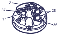
Parts of the compressor back cover.
For removal:
- It is necessary to grease a sealing ring 32 of a new reducing valve and relative details with a pure refrigerating oil of mark 525 if the system of air-conditioning is filled with refrigerant R-12, or oil PAG if the worker a body of the conditioner is refrigerant R-l34a. To establish the new valve and to tighten its moment 7,5-10,5 Ќм.
- To pump out air from the system of air-conditioning and to fill it with refrigerant.
- To check up tightness of the system of air-conditioning.
 High and low pressure switches
Necessary adaptations: nippers for installation of spring rings, a stripper for sealing rings, the connecting adaptation.
For removal:
- It is necessary to unload the system of air-conditioning.
- To disconnect electric plugs from switches.
- To remove spring lock rings with the help of nippers.
- To take out switches 28.
- To take out from jacks of switches sealing rings 33 with the help of a stripper.
Attention: If the same valves will be established, it is necessary to use only new sealing rings. It is desirable to replace with new and lock rings also. In complete sets of spare switches there are new sealing and lock rings.
For installation:
- To check up cleanliness of adjusting jacks of switches of pressure and flutes of sealing rings in a back cover of the compressor. If necessary to remove all pollution. To establish the new sealing ring greased with pure refrigerating oil 33 in an assembly flute in a jack of the switch.
- To grease with pure refrigerating oil the case of the switch 28 and cautiously to insert it into a jack against the stop.
- With the help of nippers to establish a lock ring 35 by convex side inverted to the switch. Be convinced of reliability of planting of a ring in an assembly flute. Check up tightness of condensation.
 Control valve in gathering
Necessary adaptations: nippers for installation of spring rings.
| ||||||||||||
For removal:
- It is necessary to unload the system of air-conditioning.
- To remove a spring lock ring 35 with the help of nippers.
- To take out the valve 16 in gathering.
For installation:
 Back cover, lining, distributive plate, valve plate with blade valves and a sealing ring.
Necessary adaptations: the connecting device.
For removal:
- It is necessary to unload the system of air-conditioning and to dismantle the compressor of the automobile. To merge oil from the compressor, to measure its volume and to write down. To pour out oil.
- To remove a driven coupling disk 8, a pulley 19, the bearing 9 and an electromagnet 6.
- To turn out six coupling bolts 20 of the compressor and to take out them together with linings 21. Linings to throw out.
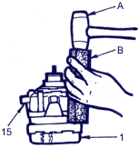
- With the help of a hammer with plastic brisk and wooden bar, to test perimeter of a back cover 1 to separate it from the block of cylinders 23 of the compressor. To remove a back cover 1, a lining 3, a distributive plate 4, valve plate 5, with blade valves and a sealing ring 24. A lining and a sealing ring to throw out.
|
For installation:
- To put a back cover 1 on a clean flat surface, having focused the valve 16 to itself (in position of a pointer of a dial on 6).
- To insert directing pins into the assembly apertures appropriate to positions of a pointer on a dial of an aperture, the pointers appropriate to positions on a dial at 5 and 11 hours.
- To put a lining 3, having arranged the lengthened aperture above the left "11-hour" pin.
- To put a distributive plate 4, having arranged the lengthened aperture above the left "11-hour" pin. To lower a plate in boring of cover 1.
- To put a valve plate 5. To take out the right "5-hour" pin.
- To grease a new sealing ring with 24 refrigerating oil of mark 525 and to set it up in a flute of the block of cylinders. It is recommended to grease for simplification of assembly with refrigerating oil a condensed surface of a back cover.
- After installation of a sealing ring 24 in a flute of the block of cylinders to arrange the block inflow for directing finger of the compressor in position " 11 hours " which should settle down but above the block aperture in a back cover. To set up causiously by putting on directing finger, the block of cylinders and crack case on a back cover.
- Having pressed from above on crack case two hands, to besiege the block of cylinders in boring a back cover against the stop.
- To set up coupling bolts 20 with new linings 21. Be convinced that four coupling bolts has screwed in a back cover of the compressor before taking out directing pins. To tighten all bolts, passing from one opposite bolt to another moving on a circle. The tightening torque should be increased gradually. The moment of a final screwing is 84 Ќм.
- To establish the new complete set of details 12, 13, 14 units of condensation of a shaft.
- To fill the compressor with refrigerating oil of mark 525 in amount which was determined in operation at disassembly of the compressor. To set up connecting device. To screw on a shaft a nut 11 and to turn a shaft by hand some times.
- To check up tightness of the compressor.
- To remove a nut 11 and to mount the coil of an electromagnet 6, a pulley 19, the bearing 9, a lock ring K, driven coupling disk 8, a nut 11.
- To install the compressor on the automobile.
- To pump out air and to charge system of conditioning with the refrigerant.
 Sealing ring between the block of cylinders and crack case
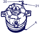
Necessary adaptations: connecting device, cylinder fixture, support.
For removal:
- To unload the system of air-conditioning and to dismantle the compressor from the automobile. To merge oil from the compressor, to measure its volume and to write down. To pour out oil.
- To remove a driven disk of coupling 8, a pulley 19, the bearing 9 and an electromagnet 6.
- To remove condensation 13, 14. Condensation to throw out.
- To turn out six coupling bolts 20 compressors to take out them together with linings 21. To throw out linings.
- With the help of a hammer with plastic brisk and wooden bar, to test perimeter of crack case 15, to separate it from the block of cylinders 23 of the compressor.
- To remove the crack case 15 from the block of cylinders 23 and a sealing ring 22. A sealing ring to throw out. To replace position of distance bushing 25, rings 26, persistent bearing and the bearing 27 for correct further assembly.
For installation:
- To put a back cover 1 on a support - A, having focused the valve 16 to itself (in position of a pointer of a dial on 6). To establish one of fixtures in an aperture of the cover located on "11 hours".
- To grease a new sealing ring with 22 refrigerating oil of mark 525 if system KB is filled with refrigerant R-12, and oil PAG if the system works on refrigerant R-134a. To set up a sealing ring in a flute of the block of cylinders.
- To set up distance bushing 25, rings 26, persistent bearings and the bearing 27 in the same order as they settled down before disassembly.
- To center inflow of an aperture for directing pin in crack case with fixture and, having pressed on crack case two hands to connect it to the block of cylinders 23.
- To put on bolts 20 the new linings 21 and to turn bolts. Be convinced that four coupling bolts are screwed in a back cover of the compressor before taking out fixture. To tighten all bolts, passing from one opposite bolt to another and moving on a circle. The tightening torque should be increased gradually. The moment of a final tightening is 8-10 Ќм.
- To establish the new complete set of details 12, 13 and 14 units of condensation of a shaft.
- To fill the compressor with refrigerating oil 525 if system KB is filled with refrigerant R-12, and oil PAG if the system works on refrigerant R-134a. The amount of oil should correspond to the volume determined above (at disassembly of the compressor).
- To check up tightness of the compressor.
- To remove a nut 11 and to mount the coil of an electromagnet 6, a pulley 19, the bearing 9, the lock ring 18, a conducted disk of coupling 8, a nut 11.
- To set up the compressor on the automobile.
- To pump out air and to charge the system of air-conditioning by the refrigerant.
 Tightness check
Necessary adaptations: manometer adapters, the connecting adaptation, the detector of outflow.
For check:
- To set up the device on a back cover of the compressor.
- To attach the central aperture of a collector of manometers on the charging station to capacity with the refrigerant, installed vertically. To open the valve of capacity.
- To attach pipelines of high and low pressure of the charging station to the appropriate unions of the adaptation. To use adapters of manometers or tips with devices of valve release. The entrance aperture 2 of the compressor has greater diameter in comparison with day off.
- To open cranes of low and high pressure, and also the crane of release of the refrigerant on a filling station in order to inflate cavities of the compressor with the refrigerant pressure vapor.
- With the help of the detector of outflow, to check up tightness of condensation of joints of crack case with the block of cylinders and the block of cylinders with a back cover, linings of coupling bolts, sealing unit of a shaft of the compressor, condensation of reducing valve and switches. After end of check to close cranes of low and high pressure on the charging station.
- At detection of outflow to find the reasons of untightness and to remove them. To carry out the repeated check of tightness of the compressor.
- To weaken connections of a collector of manometers with the adapters established in contours of high and low pressure, for reduction of pressure of the refrigerant vapor in the compressor. At use of the pipelines equipped with tips with devices of valve release, it is necessary to weaken connections at a collector of manometers.
- To disconnect both adapters of manometers or tips from the adaptation and to dismantle the adaptation.
 Backlashes and tightening torques of screw joints
|
Special tools and devices
 |
|
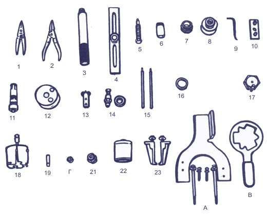
1 Ц nippers for installation of spring rings |
|

