
| NEWS | |||||||
| ABOUT | |||||||
| PRODUCTS AND SERVICES | |||||||
|
| |||||||
| PLACE AN ORDER | |||||||
| DOWNLOAD | |||||||
| HELPFUL HINTS | |||||||
| FAQ | |||||||
| LINKS | |||||||
| SEARCH | |||||||
| SITE MAP | |||||||
| CONTACT | |||||||
| русский |
Compressor repair
At servicing the compressor it is necessary to remove only those details which require under repair or replacement. Removal and installation of external details of the compressor, and also disassembly and assembly of internal units should be made on a clean workbench. The workplace, tools and details should be kept clean constantly.
|
|
Attention: Not apply the big efforts and not knock on a nave or a shaft. It may result in damage of details of the compressor.
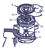
- Turn out the central bolt from the adaptation - E and turn the case of a stripper on 180 degrees.
- Screw the case of a stripper - E on the central bolt so that last could be screwed on a carving shaft of a shaft.
- Keeping the central bolt a key and turning the case of the adaptation - E, spread a nave on a shaft. Having turned on some revolutions the case, remove the adaptation and be convinced, that feather 10 is in a flute. Then finalize a nave on a shaft. Backlash between disks of coupling should make 0,38-0,64 mm.
- If the central bolt is screwed on a shaft against the stop or if to keep the case of the adaptation and to screw the central bolt, feather will jam and will block a nave.
- Remove adaptation E and check up position of feather. Feather should settle down in level with or support an end face of a nave slightly. Screw a nut 11 on a shaft of a shaft. Keeping a nave from rotation with the help of a key C, turn with muff - D a nut 11. Final inhaling is made with dynamometric key with the limiting moment 35 Нм.
- Turn manually a pulley and check up absence of catching for a driven disk.
 Bearing pulley unit
Necessary adaptations: nippers for installation of spring rings, a stripper of the bearing, the adaptation for installation of the bearing, the universal assembly handle, a stripper of a nave and a disk of coupling, a stripper of a pulley, an emphasis of a stripper and a support.
For removal:
- To disconnect a disk of coupling and a nave in gathering.
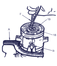
- To remove a spring lock ring 18 with the help of nippers for spring rings F.
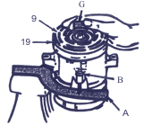
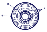
- To set the support of a stripper (G) on an end face of crack case 15 compressors. To set a stripper - H on a disk of a pulley so that face captures have come in ring grooves of a disk - a. To turn a stripper - H on hourhand to a pointer that captures were included in gearing with sectors between grooves of a disk.
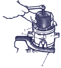
- Keeping a stripper - H on a place to screw a bolt and to remove a pulley 19 with the bearing 9 in gathering.
- To prevent damage of a disk of a pulley during dismantle of the bearing, it is necessary to provide a support to a nave of a pulley.
- To turn out a bolt from a stripper and, not removing the adaptation - H from a disk of a pulley to set it on a firm basic surface in the turned position.
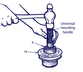
- With the help of a stripper - A and the universal assembly handle, to dismantle the bearing from a nave.
- For dismantle of the bearing there is no necessity in removing persistent fillets in an aperture of the nave, received by cerite-top. However, before installation of the new bearing it is necessary to cut these fillets with a file. Otherwise, the bearing may be damaged.
For installation:
- Turn a pulley and to set it on a support.
Attention: At installation of the bearing it is forbidden to bear an edge of a pulley on a flat surface. It will result in deformation of a disk of coupling.
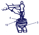
- Direct the new bearing in an aperture of a nave and also set it in a jack with the help of the assembly adaptation - J and the universal assembly handle.
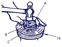
- Set up a directing A and a core - B in an aperture of a nave of a pulley. Bear a nave on a support so that the nave had a support under that place where the core is located. For deduction of a core in directing it is possible to use a bandage from strong rubber - C. After each impact by a hammer it is necessary to correct position of a core in directing.
- Set up a directing A and a core - B in an aperture of a nave of a pulley. Bear a nave on a support so that the nave had a support under that place where the core is located. For deduction of a core in directing it is possible to use a bandage from strong rubber - C. After each impact by a hammer it is necessary to correct position of a core in directing 120°.
- Set up a pulley in gathering with the bearing on crack case of the compressor. The compressor should be fixed thus in arm J34992.
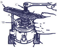
- Set up ring A and support D directly on an internal ring of the bearing 9.
- Set up assembly traverse B on a support D. Insert from both sides in traverse edges the assembly bolts with washers and screw them in apertures of arm E. Bolts should be screwed -in on full thickness of an arm.
- Rotating the central persistent bolt of traverse B, completely press a pulley 19 in gathering with the bearing 9 on crack case 15 of the compressor. At displacement of a ring A from an internal ring of the bearing 9 it is necessary to weaken a persistent bolt C of traverse and to center a ring A and support E on an internal ring of the bearing.
- Set up a spring lock ring 18 with the help of nippers for spring rings.
- Set up on its place a driven disk of coupling in gathering with a nave as it mentioned above.
 |
 |
 |
 |
 Coil of coupling electromagnet
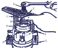
Necessary adaptations: assembly traverse of the central persistent bolt, support of a stripper, mounting cartridge of an electromagnet, captures, an arm of the compressor for installation in a vice.
For removal:
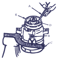
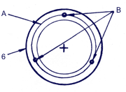
- It is necessary to execute the operations described in the previous paragraph. Note an arrangement of the coil leads 6 relatively to crack case 15 - A.
- Set up on crack case the compressor a support B. Set up the assembly traverse with captures - C.
- Wrapping the central persistent bolt - D, remove the coil of an electromagnet.
|
For installation:
- Set up the coil of an electromagnet on landing crack case neck, having focused it on a label on crack case.
- Set up the assembly cartridge in an aperture of the coil and center it relatively to crack case.
- Center traverse E concerning the central aperture of the cartridge. Insert bolts with washers in traverse edges and screw them in an arm of the compressor. Bolts should be screwed in on full thickness of an arm.
- Rotating the central persistent bolt - D of traverse, press the coil 6 on crack case neck of the compressor. It is necessary to watch that during installation the cartridge and the coil remained coaxial.
- After installation of the coil on a place dismale it with the help of a core (diameter is about 3 mm) for fixing from displacement. Punch in three places in regular intervals located on a circle through 120°.
- Size of cerite-top point should not exceed half of area of brisk. Punch depth should make 0,28-0,35 mm.
- Set up a pulley 19 in gathering with the bearing and a driven disk 8 with a nave as it mentioned above.
|
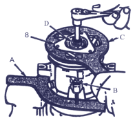 Figures which illustrate the description of repair operations, for the greater clearness are given for the compressor removed from the automobile.
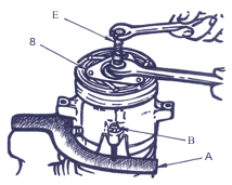 Necessary adaptations: a stripper of a nave and a disk of coupling, a muff, a key, an arm, assembly bolts.
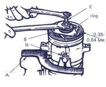 To establish feather 10 in a feather groove. Feather should act from a flute approximately on 3,2 mm. Feather is executed with small curvature for maintenance of dense landing in a flute.