
| NEWS | |||||||
| ABOUT | |||||||
| PRODUCTS AND SERVICES | |||||||
|
| |||||||
| PLACE AN ORDER | |||||||
| DOWNLOAD | |||||||
| HELPFUL HINTS | |||||||
| FAQ | |||||||
| LINKS | |||||||
| SEARCH | |||||||
| SITE MAP | |||||||
| CONTACT | |||||||
| русский |
Components of the air-conditioning system, their organization and check
|
|
|
 Checking
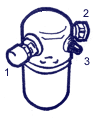
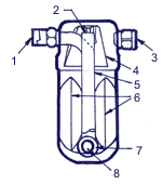
There are cases of occurrence of malfunctions of the accumulator because of internal corking. They check pressure through installing a manometer in the service auxiliary valve of low pressure located on the top part of the accumulator.
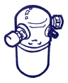 As the drier of the accumulator has good absorbing abilities, it is necessary to pay attention to the following safety measures.
For protection from contact to an atmosphere it is good to close target and entrance apertures.
At installation of the conditioner after connection of other pipelines, to attach up to air exhaust and to put after a detachment, to close immediately.
Not to mix entrance and an exhaust outlet.
Replacement needs to be made necessarily in gathering.